Federico Zani

MSc in Mechanical Engineering

3D metrology with Faro Vantage Laser Tracker

Get Started
Faro Vantage Laser Tracker

Faro Vantage E

is a portable instrument that allows fast and precise on site measurements reducing the inspection times.

3D measurements

The laser tracker measures two angles (zenith e azimuth) using built-in encoders and one distance by mean of an absolute laser beam

3D software package

Faro's CAM2 software allows fast, precise and efficient measurements

Integration

Real time measurements, flexibility / fast response / precision, automatic generation of reports

Faro Vantage Laser Tracker
01

3D measurements

measurements of complex entities (planes, pins, slots, holes, lines, tubes, ...)

02

Quality control

check piece vs. nominal dimensions

03

Manufacturing inspection

speed up geometrical tolerances verification

04

Machine installation

assure proper and precise assembly of machines or components

05

Alignment survey

check of actual alignment status for stands, machines, ...

Services

3D Inspections

3D measurements on assembled parts (even of large size)

Alignments

Alignment survey of Continuous Casting Machines

Quality control of manufactured pieces

Comparing actual dimensions with CAD model

Machines installation

Levelling to gravity with high precision
Faro Vantage Laser Tracker

F.A.Q.

  • How does the laser tracker work?

    The laser tracker measures two angles (rotation – azimuth – and elevation – zenith) and one distance: the angles (correspondent to the two axes of the measuring head) are measured by encoders while the distance is measured by a Class 1 laser beam that is reflected by a spherical target put onto the surface to be measured.

  • The distance is measured by an Absolute Distance Meter – ADM – laser beam sent from tracker e reflected by a Spherically Mounted Retroflector – SMR – put onto the surface to be measured.

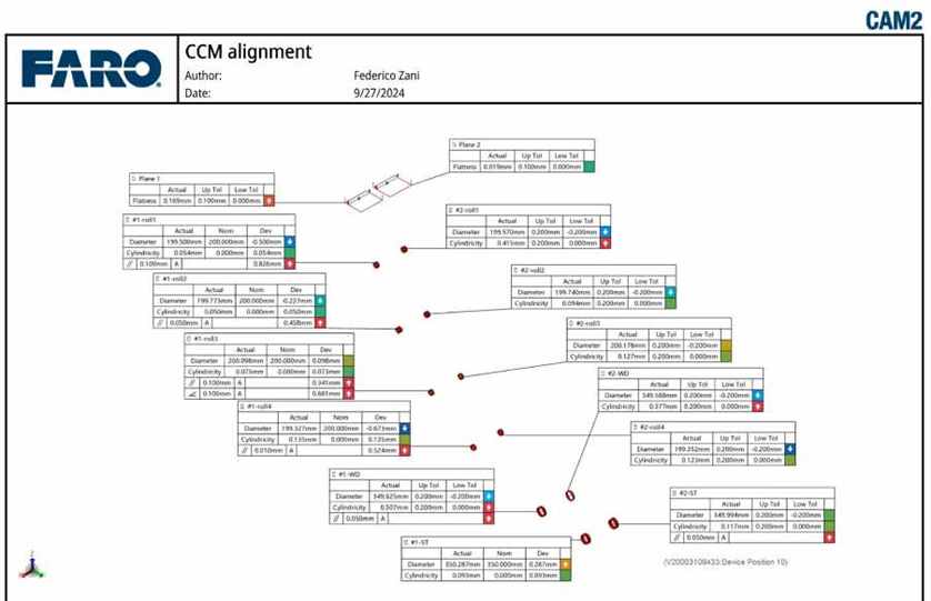
  • With CAM2 software you can measure not only points but also complex entities like planes, circles, cylinders, slots and you can construct secondary entities starting from the measured ones.

  • After importing the CAD 3D model, you can align it with the piece to measure and compare the measured entities (reality) against the nominal ones (CAD).

  • The tracker can create a very precise working level (+/- 2 arcseconds, where 3600 arcseconds correspond to 1° => 1 arcs = 0.000278°) through any reference point. Moving the SMR in the space you have a real time information of the elevation and coordinates of any point.

Contacts

Location:

via Poscolle 8C, 33100 Udine - Italy

Call: